Skip to content

Try “pit furnace”, “Fibrothal” or “electrification”.

    Case study · Electrification

    Converting a gas-fired sealed quench furnace to electric heating

    A gear manufacturer's gas-fired sealed quench furnace converted to electric heating, with elements in radiant tubes and thyristor control, running at 920–980 °C.

    Furnace:
    Sealed quench furnace
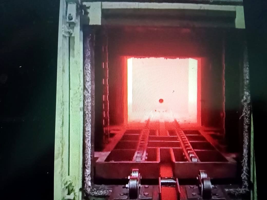
    Converted sealed quench furnace chamber glowing at operating temperature, door open

    Results

    What the project delivered.

    Heating converted in the existing furnace
    Gas → Electric
    Elements sealed off from the furnace atmosphere
    Radiant tubes
    Power and temperature control
    Thyristor
    Operating temperature
    920–980 °C

    Gas firing was replaced with electric heating elements in radiant tubes, run by a thyristor panel with temperature controllers.

    The quench, oil and charge-loading systems were kept in service: the conversion changed how the furnace heats, not how the line runs.

    Overview

    The project.

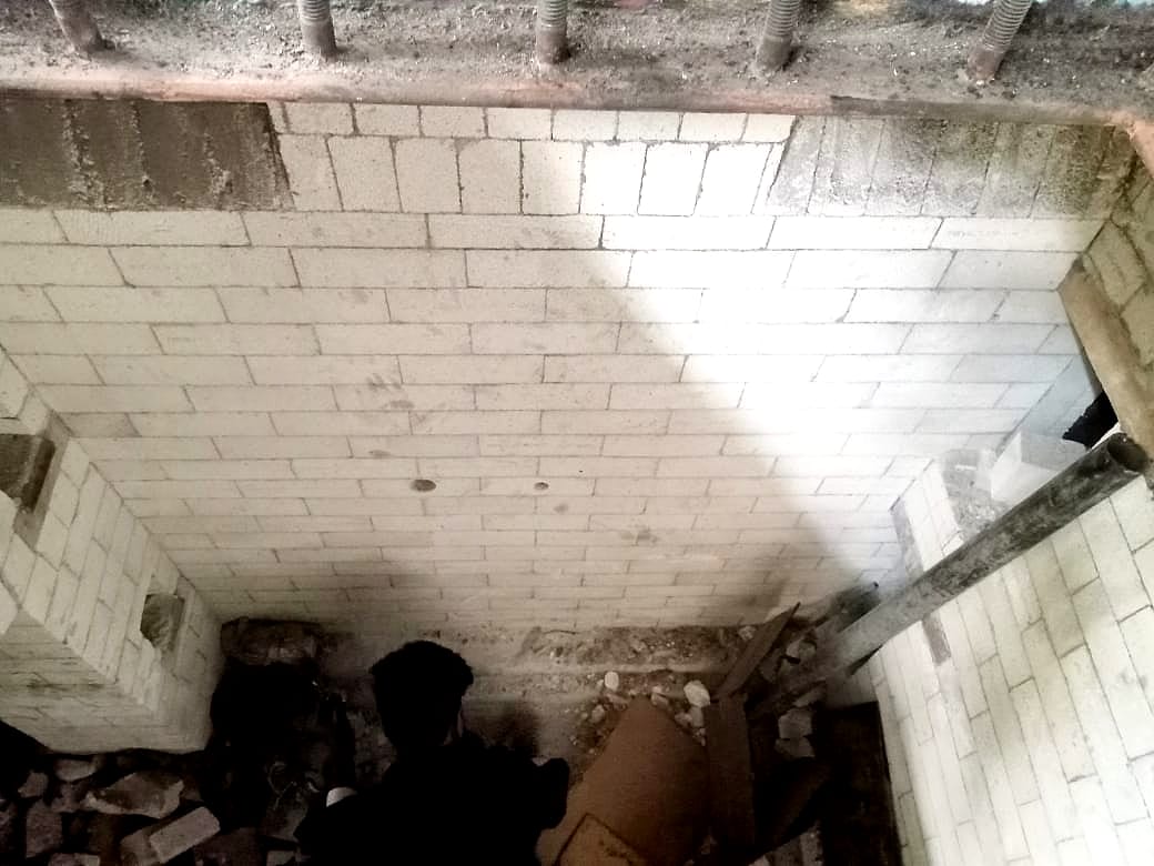
    Brick-lined chamber with lining work in progress
    Case study · Electrification

    What we did

    A gear manufacturer ran its sealed quench furnace on gas. We converted it to electric heating inside the existing furnace: refractory lining work, new radiant tube mountings, electric heating elements in the tubes, and a thyristor control panel.

    Why radiant tubes

    In an atmosphere furnace the heating elements can't sit in the furnace gas. Radiant tubes seal them off: the tube heats the chamber, while the element inside stays protected from the atmosphere.

    • CustomerGear manufacturer
    • EquipmentSealed quench furnace (SQF)
    • BeforeGas-fired
    • HeatingElectric elements in radiant tubes
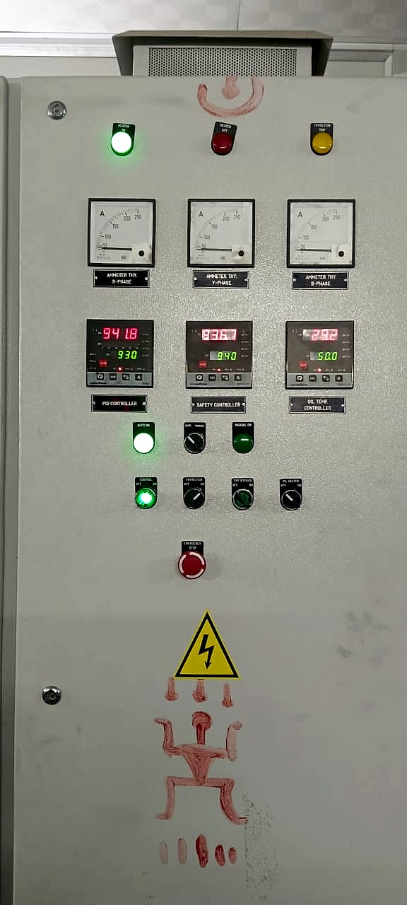
    • ControlThyristor panel with temperature controllers
    • OrderedJanuary 2022
    • Operating temperature920–980 °C
    Scope of work

    How it was done.

    1. 01

      The furnace as found

      A gas-fired sealed quench furnace, with its burner system, quench equipment and charge handling in place.

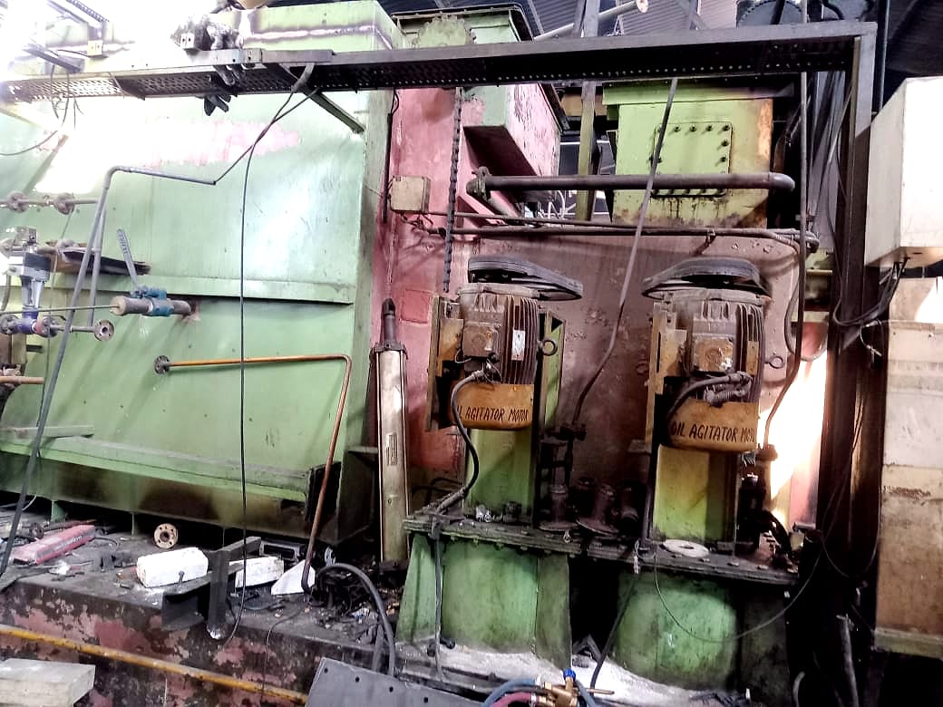
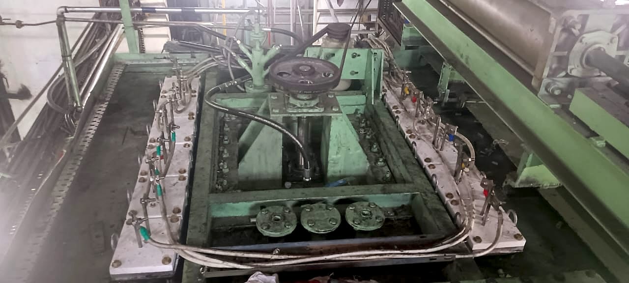
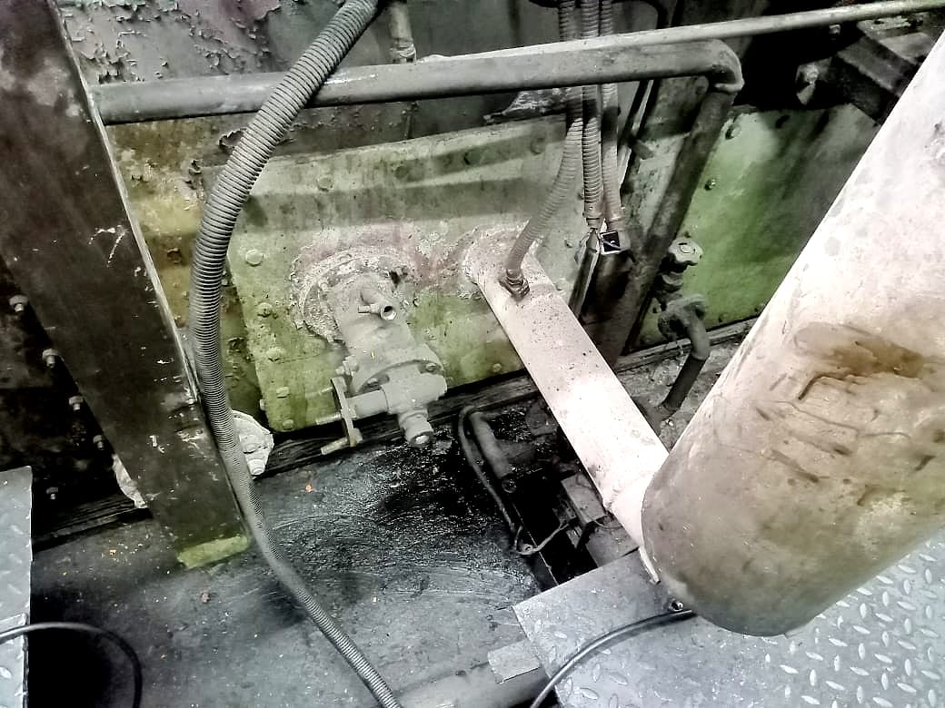
      Side of the gas-fired furnace with the quench-oil agitator motors and pipework
      Before
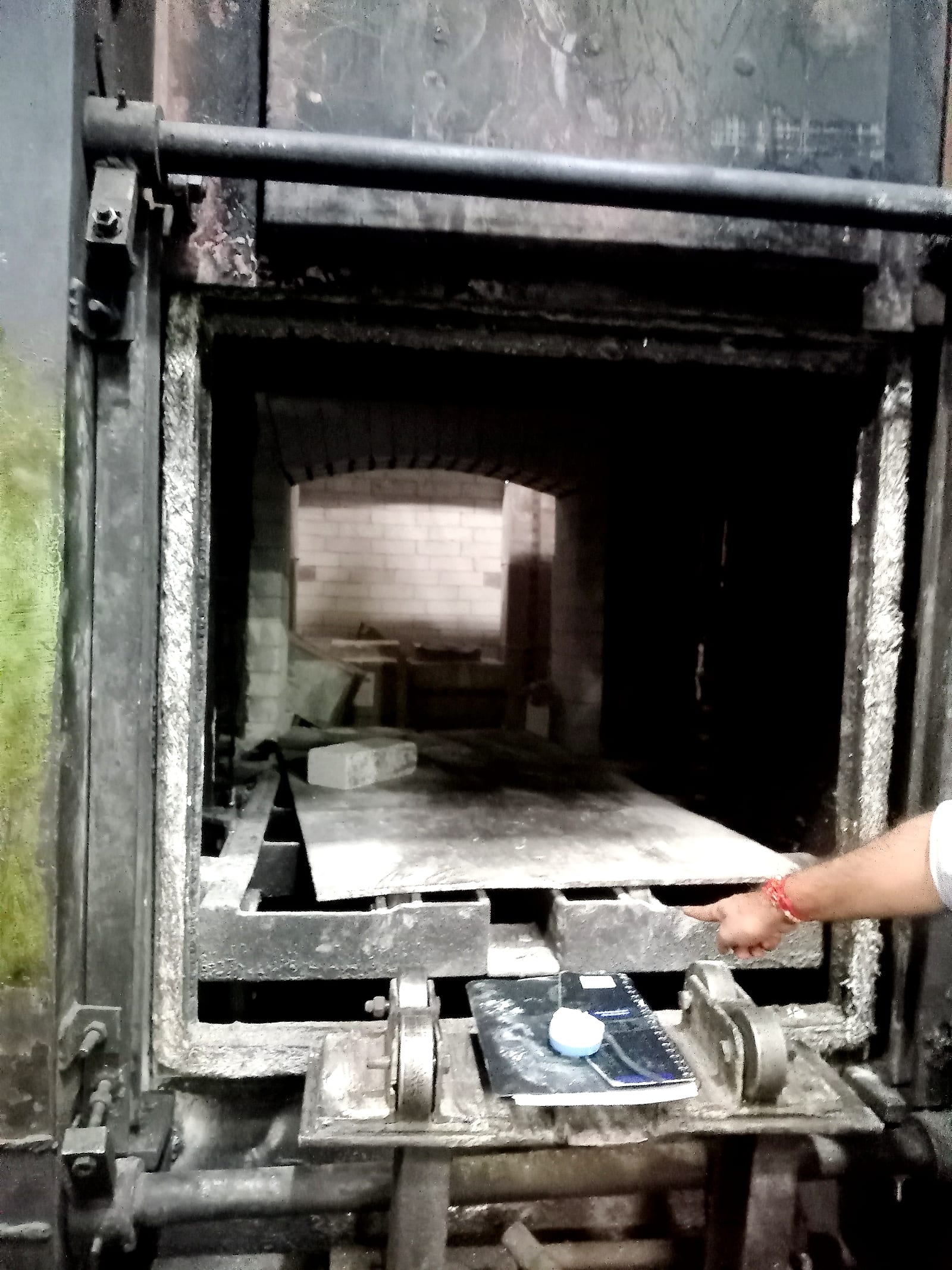
      Furnace door open on the gas-fired chamber before the conversion
      Before
    2. 02

      Systems kept in service

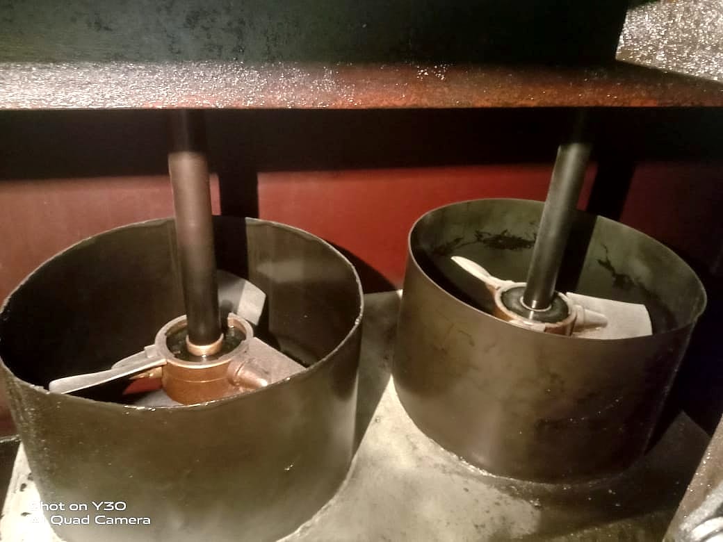
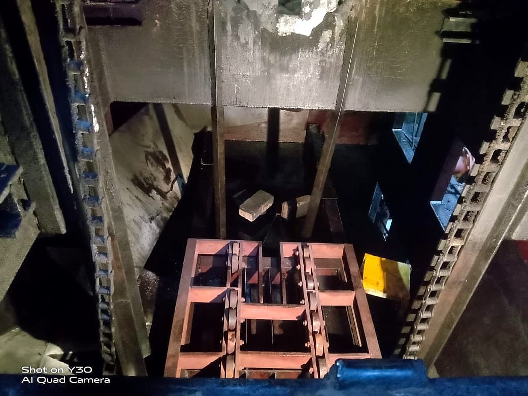
      We documented the quench-oil agitators, oil heating and charge-loading system, so the new heating fitted around equipment that stays.

      Quench-oil agitator impellers
      Agitators
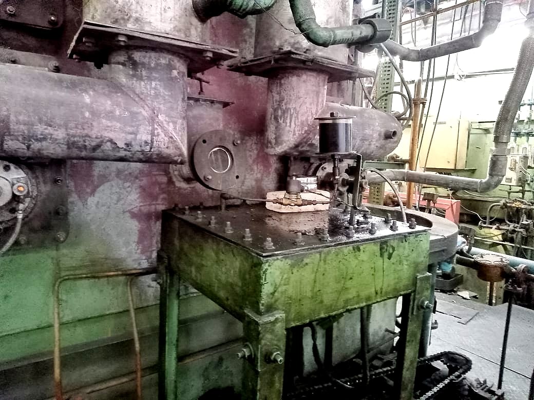
      Charge loading mechanism beside the furnace
      Charge loading mechanism
    3. 03

      Gas firing taken out

      The gas burner system was removed to make way for electric heating.

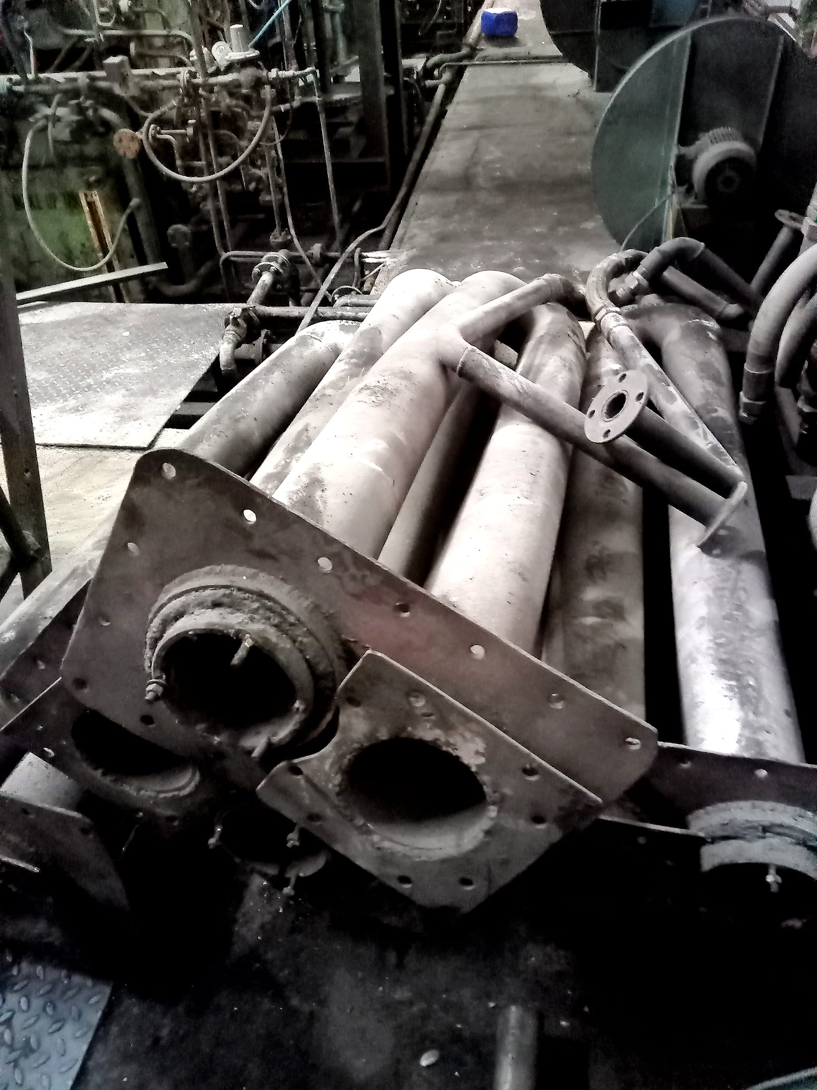
      Gas burner tubes taken out of the furnace
      Removed
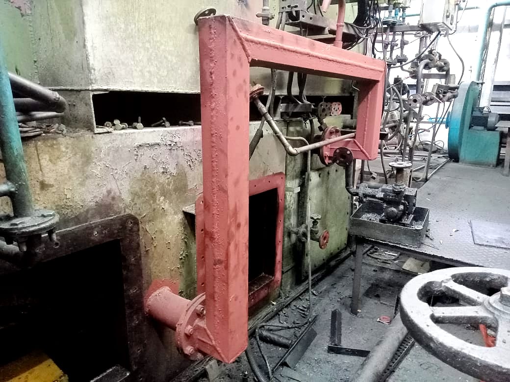
      Furnace front where the gas-fired equipment was mounted
      Before
    4. 04

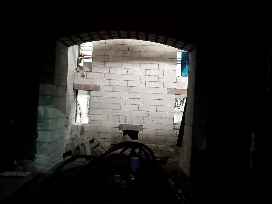
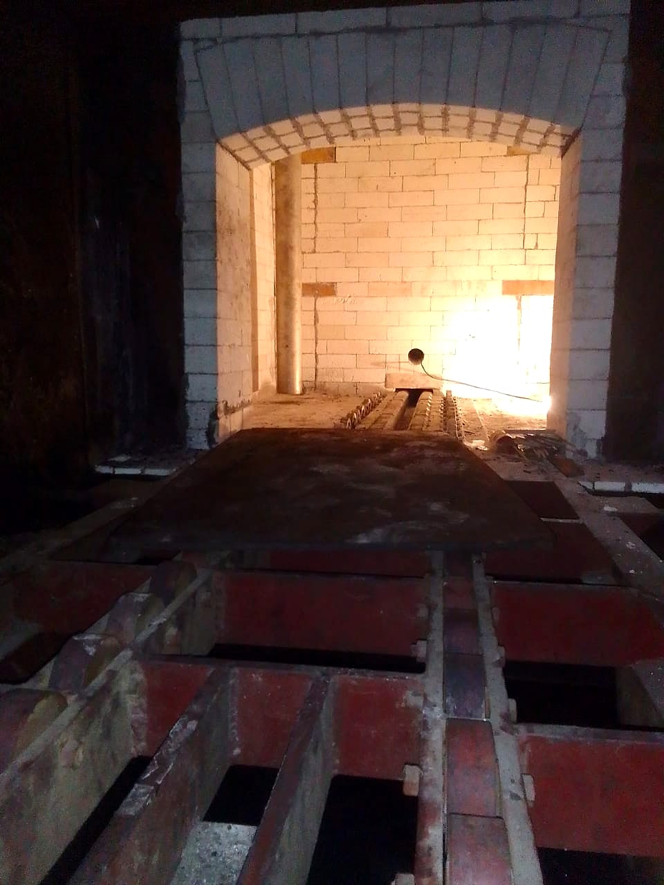
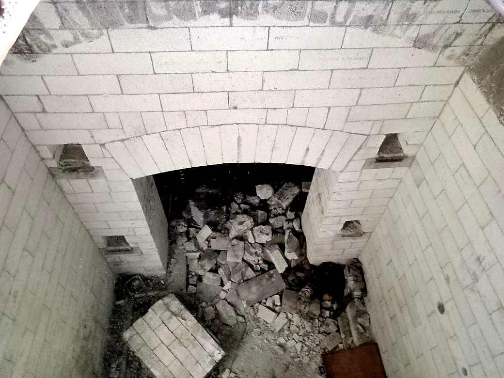
      Refractory brick lining

      Refractory brick lining work inside the chamber, ready for the new heating.

      New refractory brick lining inside the chamber, seen through the door
      Lining
      Brick-lined chamber walls during the lining work
      Lining
    5. 05

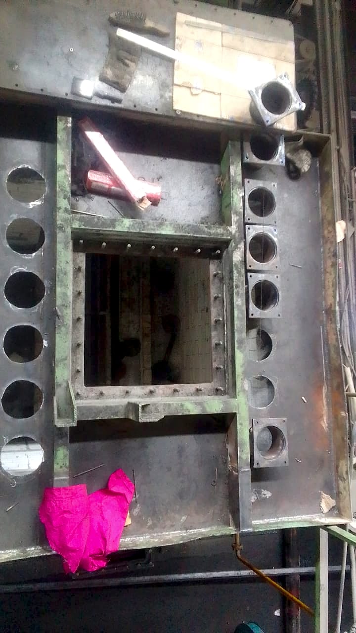
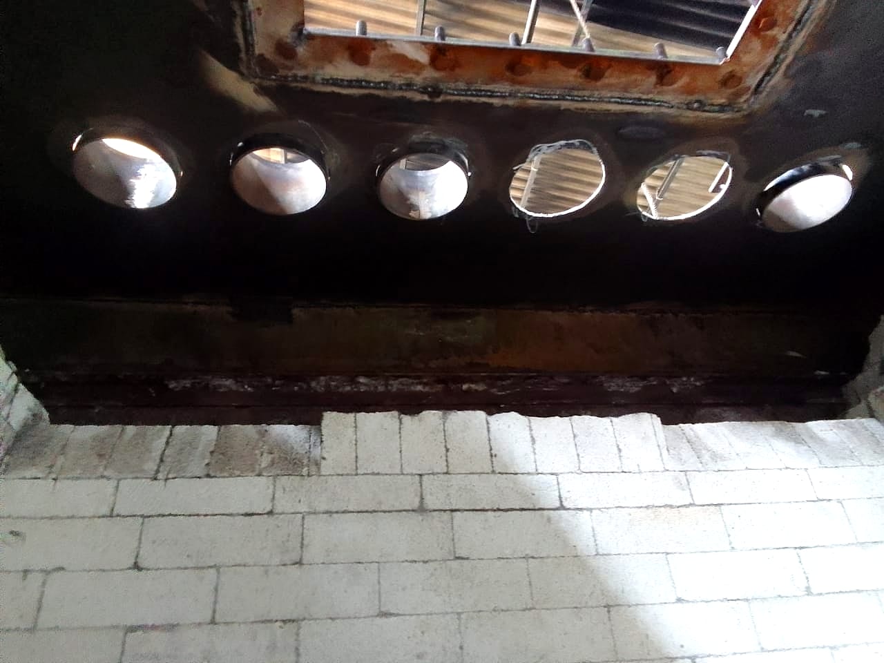
      Radiant tube mountings

      Mountings were fabricated with openings for each radiant tube.

      Fabricated mounting plate with openings for the radiant tubes
      Fabrication
      Row of radiant tube openings above the new brick lining
      Openings
    6. 06

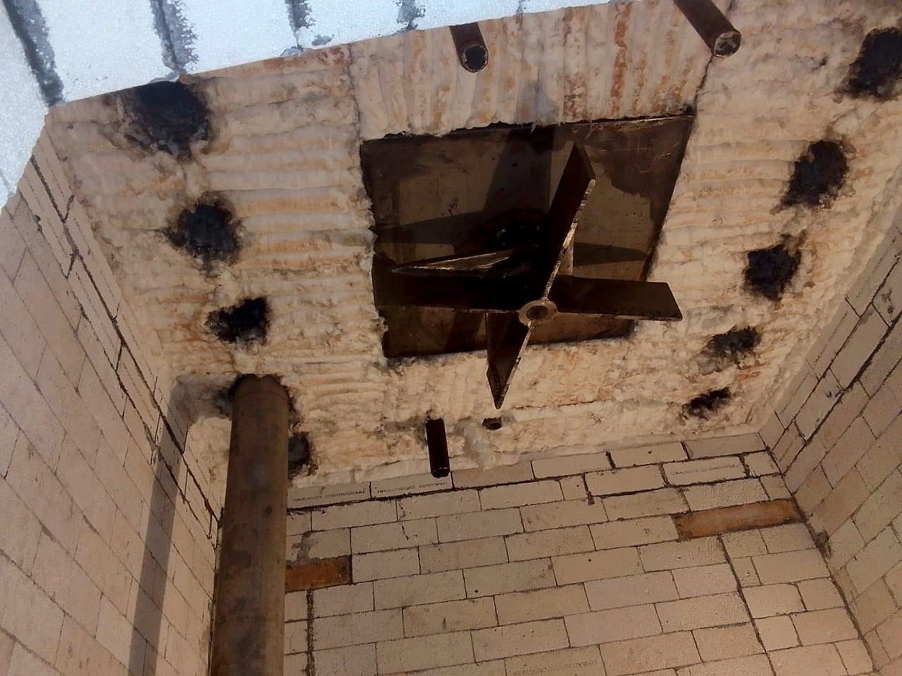
      Radiant tubes installed

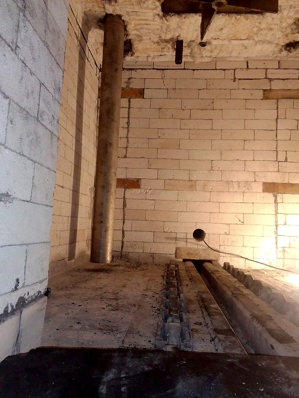
      The radiant tubes were mounted in the brick-lined chamber.

      Radiant tubes mounted inside the brick-lined chamber
      Installed
      Radiant tubes and roof openings inside the chamber
      Installed
    7. 07

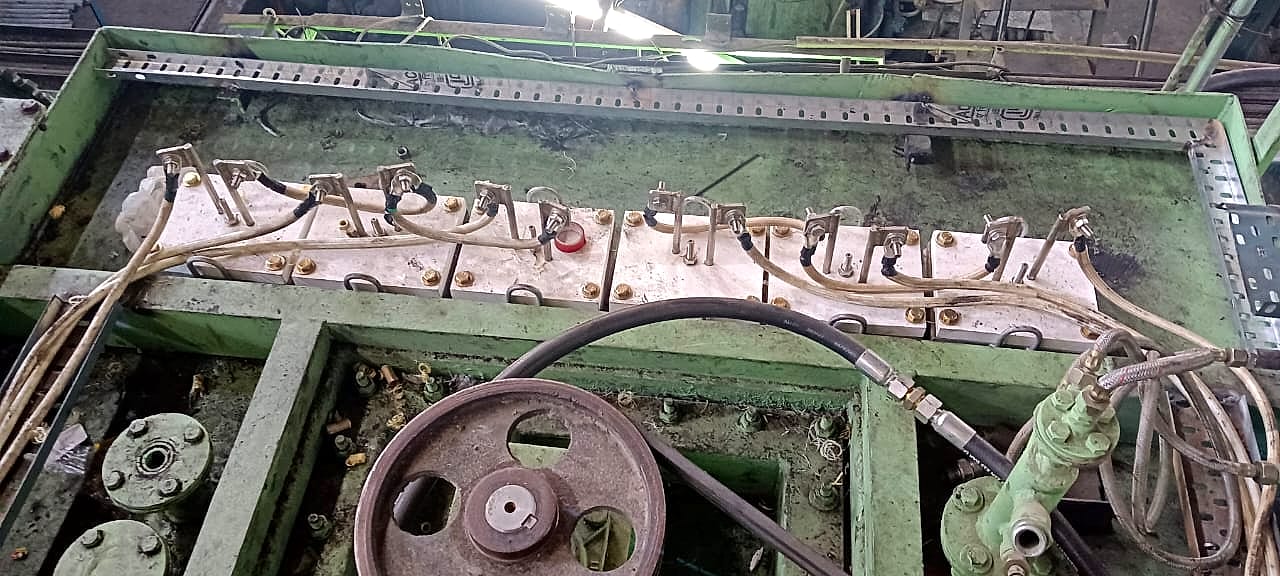
      Heating elements mounted

      Electric heating elements were fitted into the radiant tubes and wired to the new power supply.

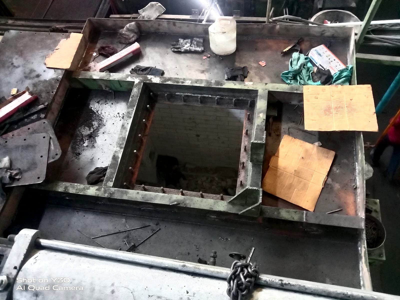
      Heating element terminals wired across the top of the furnace
      Elements
      Heating element connections on the furnace top
      Elements
    8. 08

      Control and first firing

      A thyristor panel with temperature controllers now runs the heating, holding the furnace at 920–980 °C.

      Thyristor control panel with temperature controllers and meters
      Control
      Furnace chamber glowing at operating temperature after the conversion
      At temperature

    From site

    Project images.

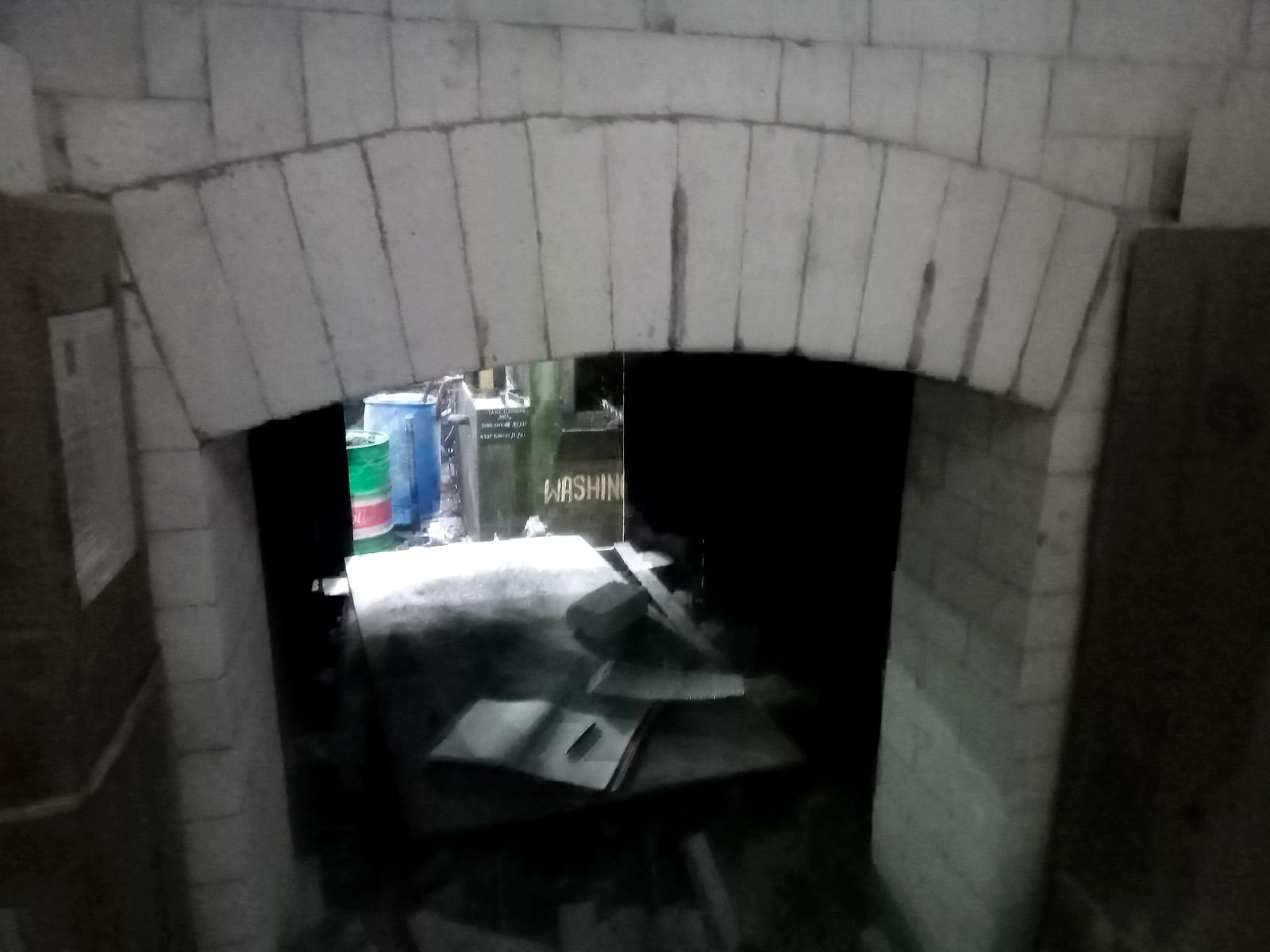
    Arched brick lining at the chamber entry
    Arched brick lining at the chamber entry
    Brick-lined chamber with lining work in progress
    Brick-lined chamber with lining work in progress
    A radiant tube standing in the lined chamber
    A radiant tube standing in the lined chamber
    Charge loading skid inside the furnace
    Charge loading skid inside the furnace
    Oil heating equipment on the quench side
    Oil heating equipment on the quench side
    Top of the furnace during the conversion
    Top of the furnace during the conversion

    Outcome

    What the client gained.

    Combustion off the shop floor

    No burners, flue gas or gas supply at the furnace.

    Elements kept out of the atmosphere

    Radiant tubes seal the heating elements away from the furnace gas.

    Temperature under thyristor control

    Solid-state power control with temperature controllers on the panel.

    Same furnace, same line

    The quench, oil and loading systems carried on as before.

    Start a project

    Have a furnace to modernise?

    Share your load, temperature and cycle time. Our engineering team will reply within two business days.

    Discuss your project

    We reply within two business days.